


In the prior post, we put together a simple "hello world" type demo.
Getting Started with ESP32 : Basic Demo
Architecture Upgrade
Using delays all over the place does not a good architecture make, so let's do some upgrades before going much further.
Breakdown
Platform - Basic Task Scheduler, Timers, Clocks, CPU-specific, etc.
Does not know about the BSP or application
I looked into some of the package options for timers and task schedulers, but really wanted an event driven system like I've used in the past.
I'm not worrying much about multi-platform at the moment either, so fine using Arduino includes rather than overdoing the abstractions.
Board Support Package (BSP) - I/O specific to my embedded system / board
- Knows about the Platform but not the application
Application - The target application
- Knows about the Platform and BSP
Diagrams
I used ChatGPT to generate some diagrams in the C4 model form.
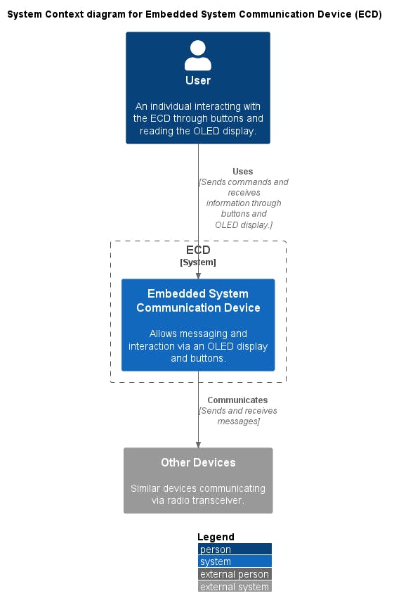
Context Diagram
A System Context diagram is a good starting point for diagramming and documenting a software system, allowing you to step back and see the big picture. In our case, we're building a small controller that is intended on using two-way communication with other devices.
Container Diagram
Once you understand how your system fits in to the overall IT environment, a really useful next step is to zoom-in to the system boundary with a Container diagram.
Within our architecture, we've divided into several layers.

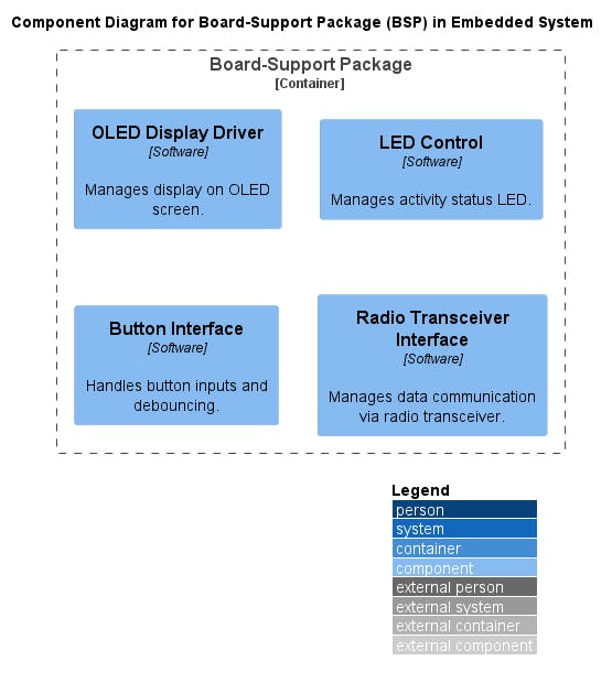
BSP Component Diagram
Diving further into the BSP, we have the following
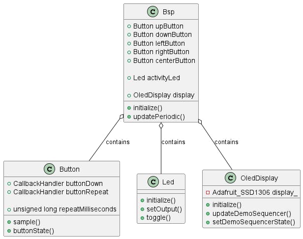
BSP Class Diagram
Note that I put application-specific content within the OledDisplay class... I'll change that in the future, but was useful for prototyping.
The button class handles sampling debounce, edge detection, and button hold. It generates events for button press and hold auto-repeat.
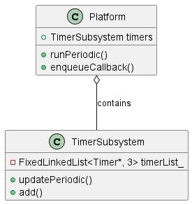
Platform Class Diagram
The platform largely contains a FIFO of callbacks function pointers and a list of timers to process. It evaluates all timers and enqueues the elapsed events.
Source
Excerpts
main.cpp
#include "app.h"
#include "bsp.h"
#include "platform.h"
#include <Arduino.h>
#include <SPI.h>


using namespace platform;

PlatformClass Platform;
bsp::BspClass Bsp;
App app;

void setup()
{
  Bsp.initialize();
  app.start();
}

void loop()
{
  Bsp.updatePeriodic();
  Platform.runPeriodic();
}
bsp.cpp
#include "bsp.h"
#include <Arduino.h>
namespace bsp {
BspClass::BspClass()
: upButton(36), downButton(39), leftButton(34), rightButton(32), centerButton(33), activityLed(LED_BUILTIN)
{
buttonList_.add(&upButton);
buttonList_.add(&downButton);
buttonList_.add(&leftButton);
buttonList_.add(&rightButton);
buttonList_.add(¢erButton);
}
BspClass::~BspClass() {}
void BspClass::initialize()
{
Serial.begin(115200);
Serial.println("BspClass::initialize()");
activityLed.initialize();
display.initialize();
}
void BspClass::updatePeriodic()
{
MonotonicTimestamp now = MonotonicTimestamp::now();
if (now > sampleTimestamp_)
{
sampleTimestamp_ = now;
sampleTimestamp_.addMilliseconds(14);
for (auto it = buttonList_.begin(); it != buttonList_.end(); ++it)
{
Button* button = *it;
if (button)
{
button->sample();
}
}
display.updateDemoSequencer();
}
}
} // namespace bsp
platform.cpp
#include "platform.h"
#include <Arduino.h>

namespace platform {

PlatformClass::PlatformClass()
{
  lastTimestamp_ = 0;
}

PlatformClass::~PlatformClass() {}

bool PlatformClass::enqueueCallback(const CallbackHandler& callback, int intValue, size_t sizeValue)
{
  return callbackFifo_.enqueue(callback, intValue, sizeValue);
}

void PlatformClass::runPeriodic()
{
  // update soft timers
  unsigned long now = millis();
  if (now != lastTimestamp_)
  {
    timers.updatePeriodic();
    lastTimestamp_ = now;
  }

  // Dequeue and execute callbacks
  while (callbackFifo_.size() > 0)
  {
    callbackFifo_.dequeueAndExecute();
  }
}

}   // namespace platform
Reference
https://github.com/ericjameszimmerman/esp32-demo/releases/tag/0.2.0
Update: Digitial Input Testing
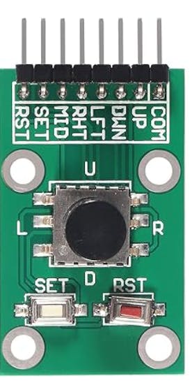
I hooked up a "5-Channel Five Direction Navigation Button Module 5D Rocker Joystick Independent Keyboard for Arduino MCU" in the following manner.
COM --> GND
UP --> GPIO32
DWN --> GPIO33
LFT --> GPIO25
RHT --> GPIO26
MID --> GPIO27
Within the demo, each button press event is tied to its own callback. A message is printed to serial output for each button press.
I needed to change the pinmode to internal pull-up and fix the edge-detection logic for active-low.
void Button::initialize()
{
  pinMode(digitalInputPin_, INPUT_PULLUP);
}

Updated Source
https://github.com/ericjameszimmerman/esp32-demo/releases/tag/0.2.1